The Kenmore washer model 110 repair manual PDF is essential for DIY repairs, offering troubleshooting, parts lists, and maintenance tips. Download it from Sears Parts Direct or other trusted sources for safe and effective appliance servicing.
Overview of the Kenmore Washer Model 110
The Kenmore washer model 110 is a popular residential washing machine known for its reliability and efficiency. Designed for automatic operation, it features a spinner-type mechanism and energy-saving capabilities. The model is supported by detailed repair manuals, parts diagrams, and genuine replacement components available through Sears Parts Direct and other trusted sources.
Importance of the Repair Manual
The repair manual for the Kenmore washer model 110 is crucial for diagnosing and fixing issues. It provides detailed instructions, safety precautions, and parts diagrams, ensuring proper maintenance and repair. Following the manual helps prevent further damage and ensures optimal performance of the appliance.
Obtaining the Repair Manual
Visit Sears Parts Direct to download the Kenmore washer model 110 repair manual PDF. Enter your model number in the search bar for easy access to the manual and resources.
Downloading the PDF from Sears Parts Direct
Visit the Sears Parts Direct website and enter your Kenmore washer model number (110) in the search bar. Follow the prompts to download the repair manual PDF, which includes detailed instructions, diagrams, and parts lists for efficient DIY repairs and maintenance.
Other Reliable Sources for the Manual
Besides Sears Parts Direct, the Kenmore washer model 110 manual can be found on trusted platforms like PartSelect and ManualsLib. These sites offer free PDF downloads, ensuring access to repair guides, diagrams, and troubleshooting tips for your appliance.
Content of the Repair Manual
The repair manual includes safety precautions, troubleshooting guides, detailed parts lists, installation instructions, and warranty information to ensure comprehensive repair and maintenance of the Kenmore washer model 110.
Safety Precautions and Warnings
Always read the manual carefully before starting repairs. Ensure the washer is unplugged, avoid overloading circuits, and use genuine parts. Follow proper lifting techniques to prevent injury and damage. Adhere to all electrical safety guidelines to ensure a safe repair process for the Kenmore washer model 110.
Troubleshooting Common Issues
Identify issues like the washer not starting, spinning, or leaking by following diagnostic steps in the manual. Check power supply, lid switches, and drain hoses. Refer to the troubleshooting guide for detailed solutions to restore functionality efficiently and safely for your Kenmore washer model 110.
Detailed Parts List and Diagrams
The manual includes a comprehensive parts list with diagrams, detailing components like washers, brackets, and bumpers. Each part is numbered for easy identification, ensuring clarity and accuracy during repairs for your Kenmore washer model 110.
Installation and Maintenance Instructions
The manual provides clear installation steps and maintenance tips, ensuring optimal performance. It covers detergent usage, proper loading, and regular checks for parts like washers, brackets, and bumpers, helping extend the appliance’s lifespan and efficiency for your Kenmore washer model 110.
Warranty Information
The manual outlines warranty details for the Kenmore washer model 110, covering parts and labor. It explains coverage duration, terms, and conditions. Sears Home Services provides support, and registering your appliance ensures warranty validity for repairs and replacements.
Troubleshooting Common Problems
The manual addresses common issues like the washer not starting, spinning, or leaking, and unusual noises. It guides users through diagnostic steps to identify and resolve problems effectively.
Washer Not Starting
If the Kenmore washer model 110 won’t start, check the power supply, ensure the lid is closed, and verify the control board. Test the lid switch and check for blown fuses or tripped circuits. The manual provides detailed diagnostic steps to resolve this common issue effectively.
Washer Not Spinning
If the Kenmore washer model 110 isn’t spinning, check for an unbalanced load, faulty lid switch, or issues with the belt or motor. The repair manual provides troubleshooting steps to diagnose and resolve spinning problems, ensuring proper function and efficient laundry cycles. Always refer to the manual for guidance.
Leaking Issues
Leaking issues in the Kenmore washer model 110 often stem from worn gaskets, damaged tub seals, or loose hoses. The repair manual provides detailed steps to identify and replace faulty parts, ensuring proper sealing and preventing water damage during operation. Follow the manual’s guidance for effective resolution.
Unusual Noises
Unusual noises in the Kenmore washer model 110, such as clunking or grinding sounds, may indicate worn bearings, loose belts, or debris in the drain pump. The repair manual provides diagnostic steps to identify the source of the noise and offers solutions, including part inspections and replacements, to restore quiet operation;
DIY Repair Guide
The DIY repair guide empowers users to fix issues independently. Essential tools and preparation steps are outlined, ensuring safe and effective repairs with clear instructions from the manual.
Essential Tools and Preparation
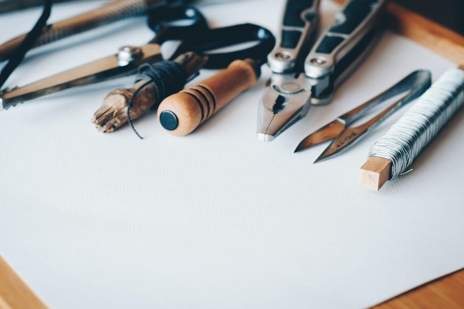
Gather essential tools like screwdrivers, pliers, and wrenches. Ensure safety with gloves and goggles. Prepare by disconnecting power and water supply. Review the manual thoroughly. Organize parts and tools beforehand to streamline the repair process. Always refer to trusted sources like Sears Parts Direct for genuine components.
Step-by-Step Repair Instructions
Disconnect power and water supply. Access internal components by removing the top or back panel. Identify and replace faulty parts using genuine components. Follow manual diagrams for proper installation. Reassemble carefully and test the washer to ensure functionality. Always refer to the manual for specific guidance.
Testing the Washer Post-Repair
After completing repairs, run a test cycle without laundry to check for leaks and proper function. Ensure all hoses are secure and verify that the spin cycle operates smoothly. Check the drain pump and electrical controls for proper operation. Run a full cycle with a small load to confirm everything works as expected, ensuring the washer is level and balanced. Consult the manual for specific post-repair testing recommendations to ensure optimal performance.
Safety Tips During Repair
Always disconnect power and water supply before starting repairs. Wear protective gloves and eyewear. Ensure the washer is stable to prevent tipping. Follow manual instructions carefully to avoid electrical shocks or injuries. Never bypass safety features, and keep children away from the repair area.
Spare Parts and Accessories
Commonly replaced parts include belts, gaskets, and bearings. Use genuine Kenmore parts for optimal performance. Sears Parts Direct and authorized dealers provide reliable access to authentic accessories and detailed diagrams for model 110 repairs.
Commonly Replaced Parts
For the Kenmore washer model 110, commonly replaced parts include tub seals, belts, drain pumps, and lid switches. Genuine Kenmore parts ensure optimal performance. Sears Parts Direct and Kenmore’s official website provide authentic components and detailed part diagrams for accurate repairs and maintenance.
How to Order Genuine Parts
To order genuine Kenmore washer parts, visit Sears Parts Direct or PartSelect. Enter your model number (e.g., 11025132411) for precise results. Use part diagrams to identify components. Follow the website’s navigation to add items to your cart and complete the purchase securely for authentic, high-quality replacements.

Preventive Maintenance
Regular cleaning, checking for worn parts, and proper detergent usage are essential for maintaining your Kenmore washer model 110. Schedule routine maintenance to ensure optimal performance and longevity of the appliance.
Regular Cleaning and Checks
Regularly clean the washer’s gasket, detergent drawer, and drain pump to prevent mold and odors. Check hoses for kinks or blockages and ensure proper ventilation. These routine checks help maintain efficiency and extend the appliance’s lifespan, as outlined in the Kenmore washer model 110 repair manual.
Proper Usage Guidelines
Adhere to load capacity limits and use detergent as recommended. Ensure the lid is closed before starting cycles. Avoid overloading, which can cause imbalance. Regularly check for proper water supply and drainage to maintain optimal performance, as detailed in the Kenmore washer model 110 repair manual.
Maintenance Schedule
Perform monthly cleaning of the washer interior and check for blockages. Inspect hoses and gaskets quarterly for wear. Ensure water supply and drainage systems are functioning properly. Regularly check and replace worn parts as outlined in the Kenmore washer model 110 repair manual to maintain efficiency and prevent breakdowns.

Safety Considerations
Always disconnect power before repairs. Use genuine parts to ensure safety. Follow manual guidelines to avoid injuries. Wear protective gear during repairs. Regular checks prevent hazards and ensure optimal appliance performance.
Electrical Safety Precautions
Always disconnect the power supply before starting repairs to avoid electric shocks. Use a voltage tester to ensure the washer is de-energized. Never attempt DIY repairs on live circuits. Ground the appliance properly to prevent electrical accidents. If unsure, consult a licensed electrician. Follow the manual’s guidelines for safe servicing.
Proper Lifting Techniques
Always bend at the knees and lift with leg muscles, not your back. Keep the appliance close to your body for better control. Ensure a firm grip and avoid overreaching. Never lift heavy components alone; use a dolly or seek assistance if necessary to prevent injury and ensure safe handling.
Avoiding Overloading
Avoid overloading the washer to prevent imbalance and damage. Check the manual for weight and size limits. Distribute clothes evenly and avoid adding too many bulky items. Overloading can cause vibrations, noise, and potential harm to the machine or surrounding structures during operation.

Warranty and Support
Understand your Kenmore washer’s warranty coverage for repairs and replacements. Contact Sears support for assistance, and rely on authorized service providers for genuine parts and expert help.
Understanding Your Warranty
Review your Kenmore washer’s warranty to ensure coverage for parts and labor. Repairs using genuine parts maintain warranty validity. Check the manual or Sears’ official website for detailed terms and conditions, and contact Sears support for any warranty-related inquiries or claims assistance.
Contacting Sears Support
For assistance with your Kenmore washer, visit Sears Home Services or call their customer support. Live chat options are also available on their official website. Ensure you have your model number ready for efficient service and genuine parts ordering.
Authorized Service Providers
For reliable repairs, use authorized Sears service providers, ensuring genuine parts and warranty compliance. These skilled technicians are certified to handle Kenmore models, providing efficient service. Locate them through Sears’ official website or trusted repair networks for professional assistance tailored to your appliance needs.
Using the Kenmore washer model 110 repair manual PDF ensures successful DIY repairs, enhancing safety and effectiveness. Refer to it regularly for troubleshooting and maintenance, maximizing your appliance’s longevity and performance with clear, detailed guidance.
Final Tips for Successful Repair
Always prioritize safety by disconnecting power before starting repairs. Use genuine Kenmore parts for reliability and consult the manual for specific instructions. Double-check connections and test the washer post-repair to ensure proper function. Regular maintenance and adherence to guidelines will extend the lifespan of your appliance effectively.
Encouragement to Use the Manual Effectively
The Kenmore washer model 110 repair manual is a valuable resource for successful DIY repairs. By following its detailed instructions and safety guidelines, you can save time, avoid costly mistakes, and ensure your appliance operates efficiently. Use it confidently to troubleshoot and fix issues like a pro!